laboratory manual for human anatomy & physiology
Introduction to Human Anatomy and Physiology
This laboratory manual is a comprehensive resource designed to guide students through a hands-on exploration of human anatomy and physiology. It provides a wide range of experiments and activities that will help students develop a deep understanding of the structure and function of the human body.
Overview of Human Anatomy and Physiology
Human anatomy and physiology are fundamental disciplines in the study of the human body. Anatomy focuses on the structure of the body, examining its various organs, tissues, and systems. Physiology, on the other hand, explores the functions of these structures and how they work together to maintain life. Understanding both anatomy and physiology is essential for healthcare professionals, researchers, and anyone interested in the complexities of the human body.
Importance of Laboratory Experiments
Laboratory experiments play a crucial role in the study of human anatomy and physiology. They provide hands-on experiences that complement theoretical knowledge, allowing students to visualize and interact with the structures and functions they are learning about. Through dissections, microscopic examinations, and other practical activities, students gain a deeper understanding of anatomical relationships, physiological processes, and the interconnectedness of different body systems.
Laboratory Techniques and Safety
This section provides essential information on laboratory techniques and safety procedures for human anatomy and physiology studies.
Basic Laboratory Equipment
The laboratory manual will introduce you to the essential equipment commonly used in human anatomy and physiology labs. This includes microscopes for observing microscopic structures, dissecting kits for exploring anatomical relationships, and various measuring tools like rulers, calipers, and scales. You will learn how to handle and use these tools safely and effectively to conduct experiments and observe specimens.
Safety Procedures and Precautions
Safety is paramount in any laboratory setting, especially when dealing with biological specimens and potentially hazardous materials. The lab manual emphasizes the importance of following strict safety protocols. This includes wearing appropriate personal protective equipment (PPE) such as lab coats, gloves, and safety goggles, handling specimens with care, and properly disposing of biological waste. The manual will also cover emergency procedures and provide guidance on how to react in case of accidents or spills.
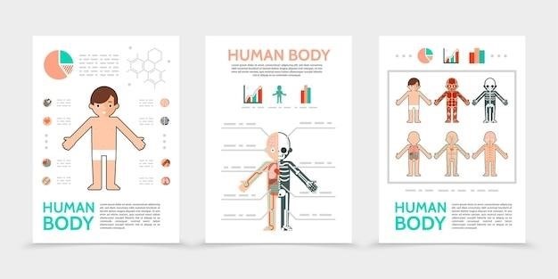
Human Body Systems
This section delves into the intricacies of the major organ systems that make up the human body.
Skeletal System
The skeletal system is a complex and fascinating system that provides support, protection, and movement for the body. This lab will explore the bones, joints, and cartilages that make up the skeletal system. You will learn about the different types of bones, their functions, and how they are connected to form the skeleton. You will also have the opportunity to examine real bones and models to understand the anatomy of the skeletal system.
Muscular System
The muscular system is responsible for movement, posture, and heat production. This lab will delve into the structure and function of muscles, exploring the different types of muscle tissue and their roles in the body. You will learn about muscle contractions, how muscles are attached to bones, and the factors that influence muscle strength and endurance. Through hands-on activities and demonstrations, you will gain a deeper understanding of how the muscular system works.
Nervous System
The nervous system is the body’s control center, responsible for receiving, processing, and transmitting information. This lab will explore the intricate organization of the nervous system, from the central nervous system (brain and spinal cord) to the peripheral nervous system (nerves throughout the body). You will examine the structure of neurons, the basic units of the nervous system, and learn about the different types of nerve cells and their functions. Through experiments and simulations, you will gain a deeper understanding of how the nervous system controls everything from movement and sensation to thought and memory.
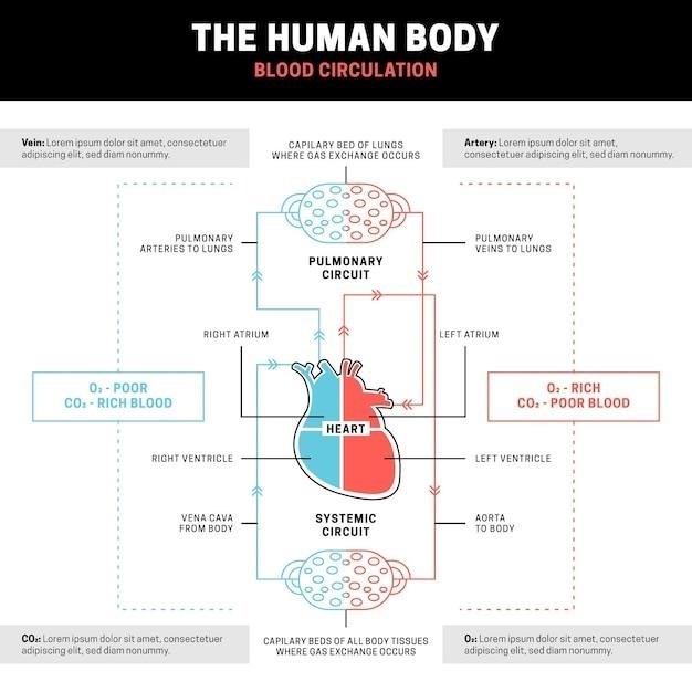
Cardiovascular System
This section delves into the fascinating world of the cardiovascular system, the body’s intricate network responsible for transporting blood, oxygen, and nutrients to every cell. You will explore the structure and function of the heart, the powerful pump that drives blood circulation. You will dissect and examine the major blood vessels, including arteries, veins, and capillaries, and learn how blood pressure is regulated. Through experiments and simulations, you will gain a comprehensive understanding of how the cardiovascular system works to maintain homeostasis and support life.
Respiratory System
This section delves into the intricate workings of the respiratory system, the vital organ system responsible for gas exchange. You will explore the anatomy of the lungs, including the bronchi, bronchioles, and alveoli, and gain a deep understanding of how oxygen enters the bloodstream and carbon dioxide is expelled. You will also examine the mechanics of breathing, including the role of the diaphragm and intercostal muscles. Through practical experiments and simulations, you will gain a firsthand perspective on the crucial role the respiratory system plays in maintaining life.
Digestive System
This section provides an in-depth exploration of the digestive system, the complex network of organs responsible for breaking down food and absorbing nutrients. You will examine the anatomy of the digestive tract, from the mouth to the anus, and learn about the various enzymes and processes involved in digestion. Through hands-on activities, you will investigate the mechanical and chemical digestion of different food types, and gain a comprehensive understanding of how the digestive system extracts essential nutrients for the body’s functions.
Urinary System
This section focuses on the urinary system, a vital organ system that plays a crucial role in maintaining fluid balance and removing waste products from the body. You will dissect and examine the kidneys, ureters, bladder, and urethra, gaining a detailed understanding of their structures and functions. Through laboratory experiments, you will explore the processes of filtration, reabsorption, and excretion, and learn how the urinary system regulates blood volume, pH, and electrolyte balance, contributing to overall homeostasis.
Endocrine System
This section delves into the intricacies of the endocrine system, exploring its role in regulating and coordinating various bodily functions through the production and secretion of hormones. You will investigate the major endocrine glands, including the pituitary, thyroid, parathyroid, adrenal, pancreas, and gonads, examining their anatomical structures and the specific hormones they synthesize. The lab exercises will focus on understanding the mechanisms of hormone action, feedback loops, and the impact of hormonal imbalances on different physiological processes, providing a comprehensive understanding of the endocrine system’s vital role in maintaining homeostasis and overall health.
Reproductive System
This section delves into the intricate mechanisms of the human reproductive system, examining the anatomy and physiology of both male and female reproductive organs. You will dissect and analyze models of the reproductive structures, identifying key components like the testes, ovaries, uterus, and fallopian tubes. Through interactive exercises, you will explore the processes of gametogenesis, fertilization, and embryonic development, gaining a deeper understanding of the complex interplay between hormones, anatomical structures, and physiological processes involved in human reproduction. This section also includes a discussion of the importance of reproductive health and the societal implications of various reproductive technologies.
Dissection and Specimen Examination
This section focuses on hands-on learning through dissection and specimen examination, providing valuable insights into the intricate details of human anatomy.
Dissection Techniques
This section provides detailed instructions and guidance on proper dissection techniques. Students will learn about the tools and procedures involved in dissecting specimens, emphasizing safety and ethical considerations. The manual will cover techniques such as making incisions, identifying structures, and handling delicate tissues, ensuring students develop the skills necessary for a successful dissection experience.
Examination of Human Specimens
This section focuses on the examination of human specimens, providing students with a hands-on experience studying real anatomical structures. The manual will guide students through the process of observing, identifying, and analyzing various human specimens, including bones, organs, and tissues. It will emphasize the importance of using proper techniques, handling specimens with care, and respecting the human body.
Virtual Laboratory Experiences
The manual incorporates virtual laboratory experiences, offering an interactive and engaging way to learn anatomy and physiology.
Advantages of Virtual Labs
Virtual labs offer several advantages for students studying human anatomy and physiology. They provide a safe and controlled environment for experimentation, allowing students to explore complex concepts without the risk of real-world hazards. Virtual labs also provide flexibility, allowing students to access and complete experiments at their own pace and convenience. Moreover, they offer a cost-effective alternative to traditional labs, eliminating the need for expensive equipment and materials. Virtual labs can also provide interactive and engaging learning experiences, incorporating animations, simulations, and other multimedia elements to enhance understanding.
Examples of Virtual Lab Simulations
Virtual lab simulations offer realistic representations of anatomical structures and physiological processes. For instance, students can explore the intricate details of the human heart using 3D models, dissect virtual specimens without the need for actual dissections, and manipulate virtual instruments to simulate physiological responses. These simulations provide engaging and interactive learning experiences, allowing students to visualize and understand complex anatomical structures and physiological functions in a more comprehensive way. Virtual lab simulations are increasingly being incorporated into human anatomy and physiology courses, providing a valuable supplement to traditional lab experiences.
Resources and Further Exploration
This section provides a comprehensive list of resources to enhance your learning journey in human anatomy and physiology.
Recommended Textbooks and References
To supplement your laboratory experiences and deepen your understanding of human anatomy and physiology, consider exploring these recommended textbooks and references⁚ “Human Anatomy & Physiology Laboratory Manual, Main Version” by Elaine Marieb and Lori Smith, “Human Anatomy & Physiology Laboratory Manual⁚ Making Connections, Main Version” by Elaine Marieb, and “Laboratory Manual for Human Anatomy & Physiology⁚ A Hands-on Approach” by Melissa Greene, Robin Robison, and Lisa Strong. These resources offer comprehensive coverage of anatomical structures, physiological processes, and essential laboratory techniques.
Online Resources and Learning Platforms
In addition to traditional textbooks, a wealth of online resources can enhance your study of human anatomy and physiology. Websites like Khan Academy, OpenStax, and Biology LibreTexts offer interactive tutorials, videos, and animations that illustrate complex anatomical structures and physiological processes. Platforms like Coursera and edX provide access to online courses taught by leading experts in the field, allowing you to delve deeper into specific areas of interest. These resources can provide supplementary learning materials, review concepts, and expand your understanding of the subject.
Professional Organizations and Societies
Engaging with professional organizations and societies can provide valuable opportunities for networking, professional development, and staying abreast of the latest advancements in human anatomy and physiology. The American Association for Anatomy (AAA), the American Physiological Society (APS), and the Human Anatomy and Physiology Society (HAPS) are prominent organizations that offer resources, conferences, and publications for professionals and students in the field. Joining these organizations can connect you with a community of like-minded individuals, enhance your career prospects, and provide valuable insights into the ever-evolving field of human anatomy and physiology.